Are we getting tired of this thing yet?! I am SO ready for it to be done... Lots of little odds and ends to tie up. Let me apologize right now in advance for this gi-mongous post... Sorry.
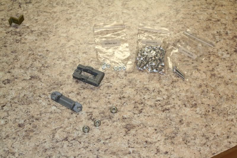
Assembling the Y idler. Here is my first complaint... this step uses 3D
printed parts- and the print quality was pretty poor on these two.
I'll explain more when we get to the pics.
Parts.
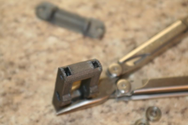
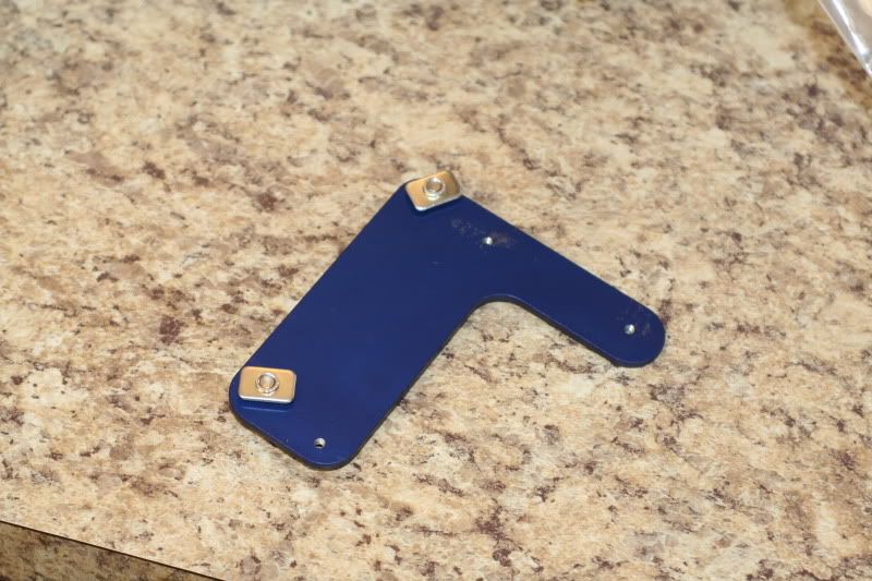
These two slots are supposed to have nuts slid into them- but as you can
see the right slot is warped. It took me a bunch of dinking around to
carve it out big enough to get the nut to fit (both sides were too small
and had to be carved out).
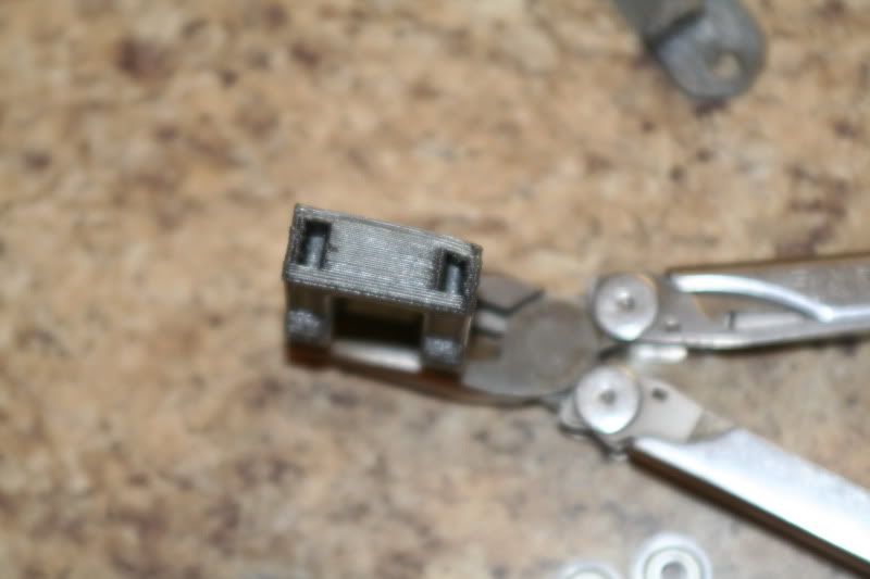
Finally got them in...
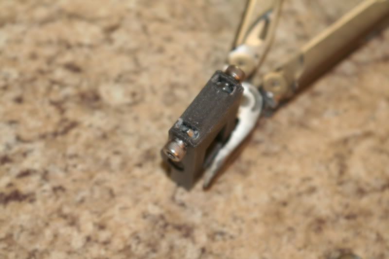
This nut went in fine, but the screw wasn't long enough to reach it so I had to drill out the other side.
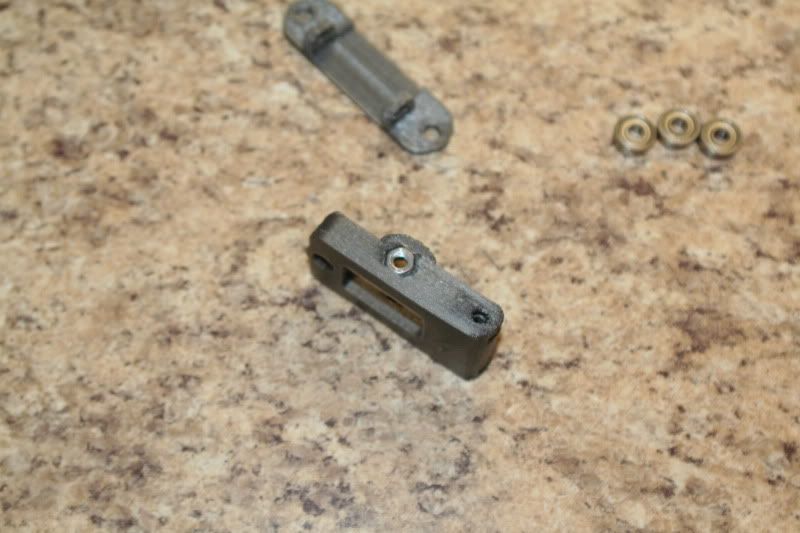
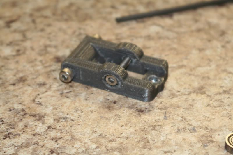
Once I got it drilled out enough, take the screw out and install the bearings.
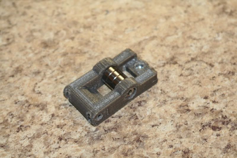
Attach the base. The instructions called for M5-8, but they wouldn't reach so I used M5-10.
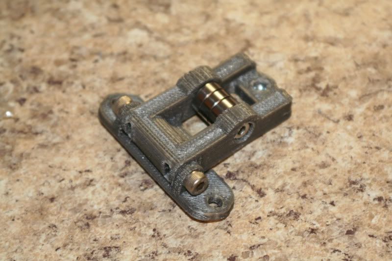
Install the tensioner nut on the back. This hole had to be carved out too...
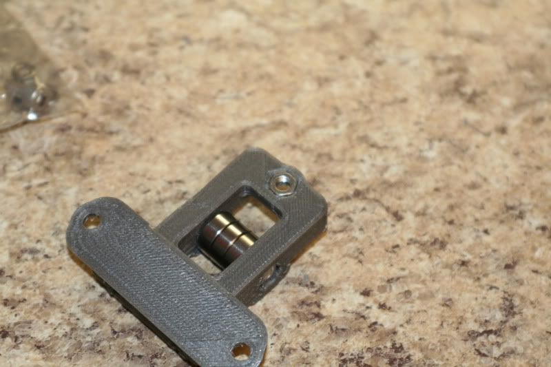
And the tensioner screw.
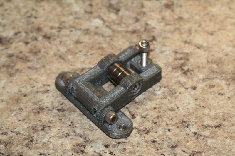
Easiest part- put it on the machine.
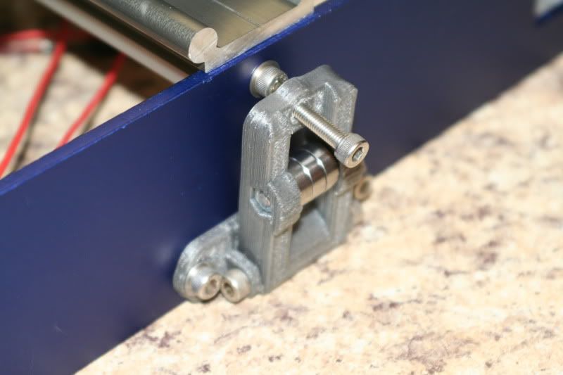
Time Spent on this step: 40 min. (should have been like 5...)
Total time so far: 6 hrs 30 min.
More fiddling and tweaking. I also spent some time adjusting things to get everything square and moving as
freely as possible. The first order of business was to free up the
x-axis- I made the mistake of tightening up the rails too soon. One of
the little screws stripped out trying to loosen them, so I had to drill
it out, slide the rail out, and replace it.
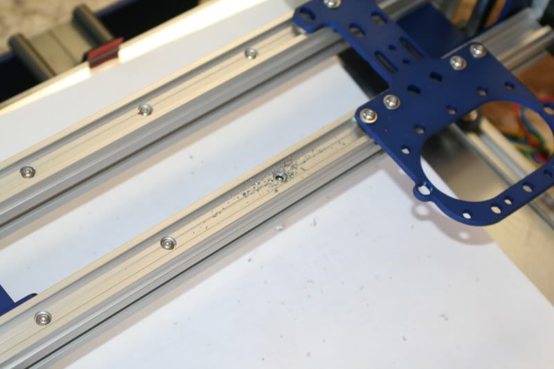
Once I had that fixed, I just slid the plate back and forth and slowly
tightened the screws until they were all tight and the plate slid back
and forth freely.
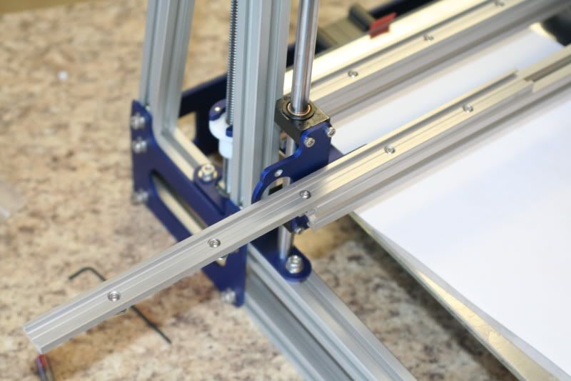
The z axis was similar. Loosened things, and slowly tightened them back
up until it seems to move freely. The thing that seemed to make the
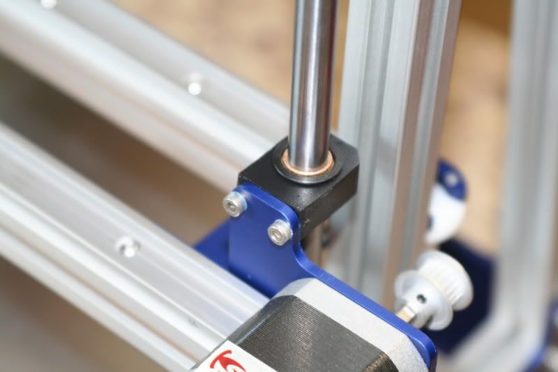
biggest difference was to not tighten these busing blocks as tightly-
they are plenty tight, just not gorilla tight.
The y-axis didn't need and adjusting- it moved very freely.
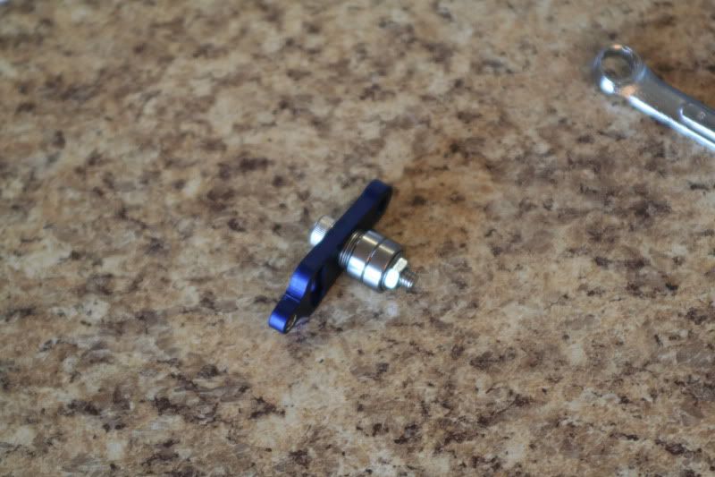
The last thing I did was fix the x idler- had to add a few washers. Here is the correct assembly.
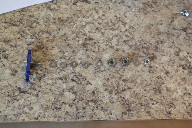
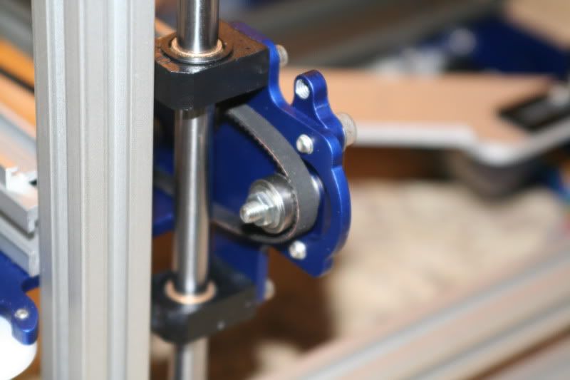
And installed.
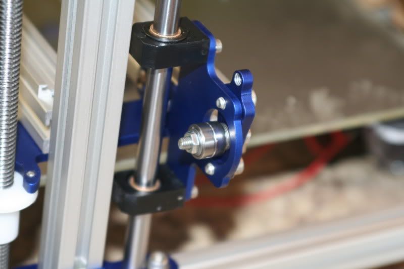
Also went over all of the nuts and bolts and checked and tightened anything I found loose.
Time Spent on this step: 1 hr.
Total time so far: 7 hrs. 30 min.
Finishing Touches! The closer I get to done the more I notice the hundreds of little things that still have to be finished...
Parts:
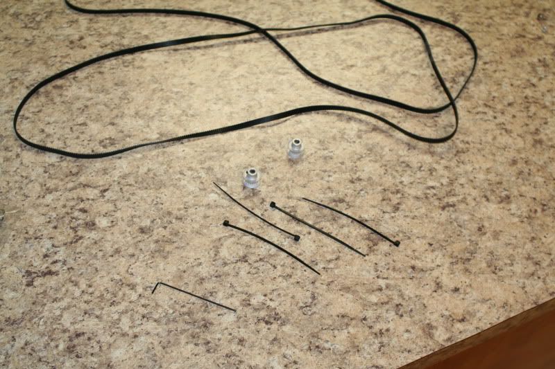
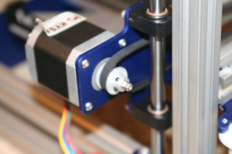
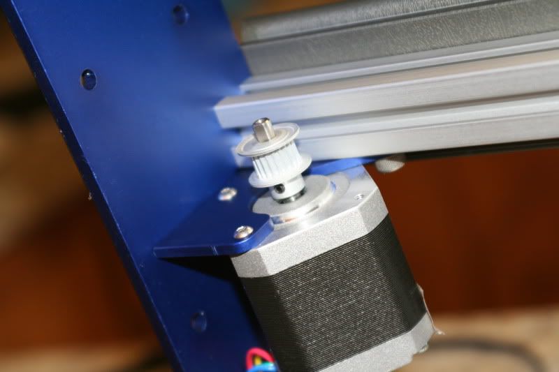
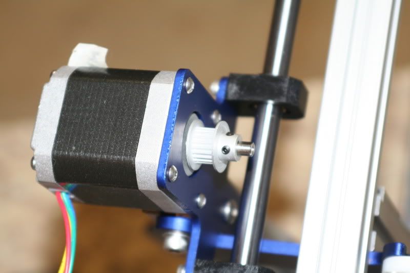
Install the pulleys. They have to be oriented a certain way to line up with the axis and idlers.
Y-axis:
X-axis:
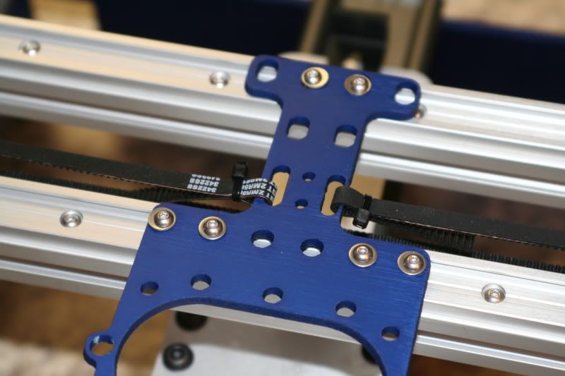
Cut the belts.
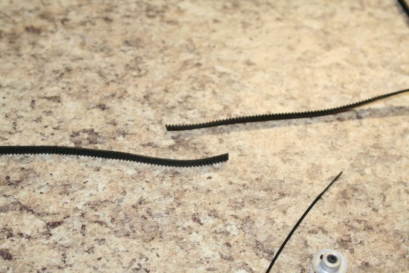
Attach one end to the axis plate. I plan on adding another zip tie and trimming of the extra on all of the belts still. Y axis:
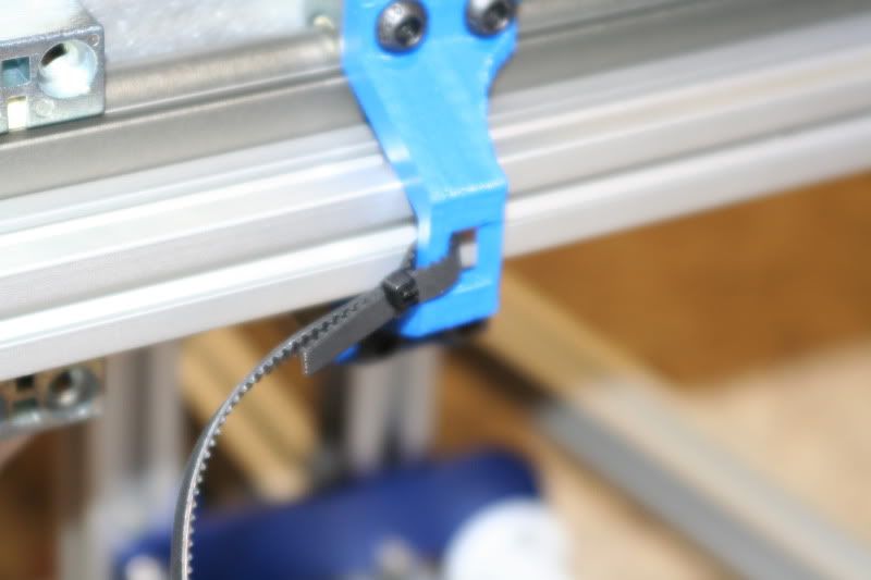
Loop it over the pulley
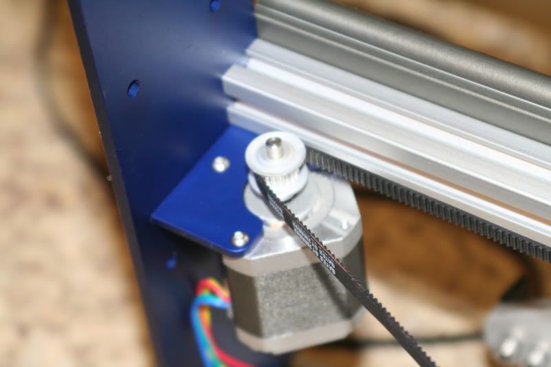
And through the idler
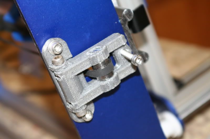
And attach it back to the axis plate.
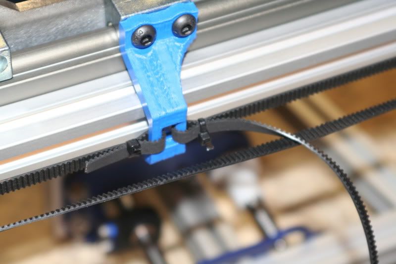
Obviously the extra belt needs trimmed off still...
Adjust the tension using the idler.
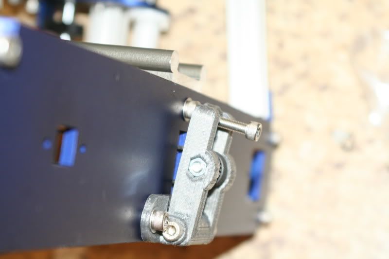
X-axis. Still need to trim the belts.
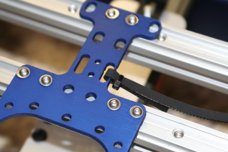
Once the belts are on, adjust the tensioners to tighten.
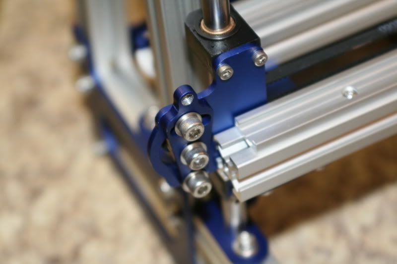
Time Spent on this step: 30 min.
Total time so far: 8 hrs.
Spent some time routing stepper motor wires and figuring out how to hook things up.
When I was talking to the company about what electronics to get, they
recommended I get the RUMBA contoller board. It looks like the mounting
brackets supplied do not work for my style of board, so I'm going to
have to make something up. Same for the power supply. Means it'll take a little longer but I feel like I'm reaaalllly close to firing it up and figuring out the software!
Electronics bracket... not designed for my electronics.
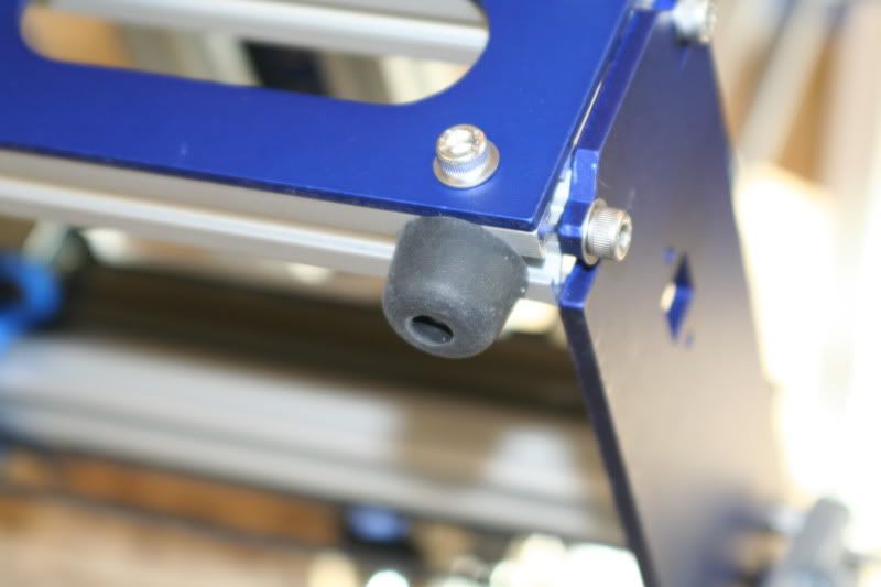
Rubber feet.
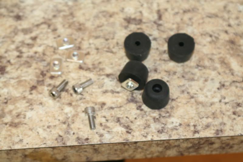
Install one foot, then the bracket, then the other feet.
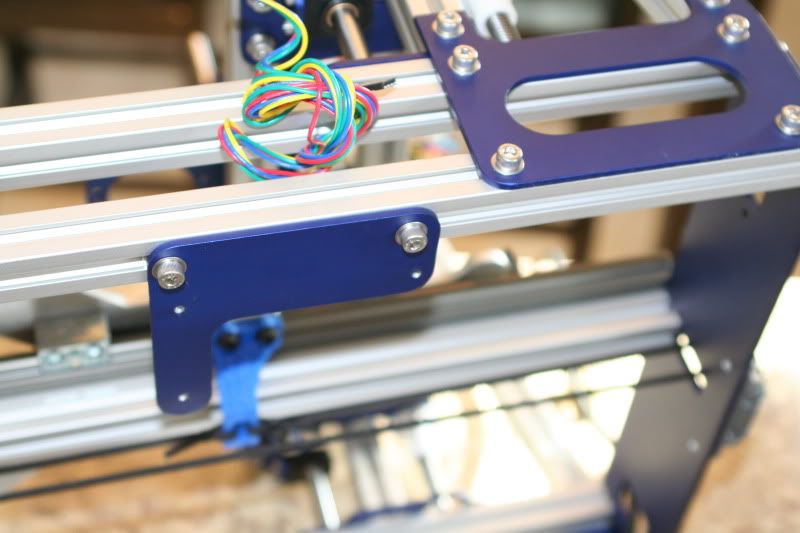
These should have all been installed while assembling the frame... The instructions have already been fixed to reflect that.
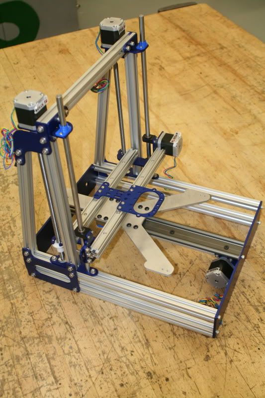
For the most part, all of the hardware is now DONE!!! I *only* have to install the electronics and get the software figured out. Sounds simple, right? NOT.
Time Spent on this step: 45 min.
Total time so far: 8 hrs. 45 min.
Friday, February 22, 2013
Wednesday, February 20, 2013
Mendelmax 2.0- Y-Axis assembly.
Assembling the Y axis. Pretty simple and didn't really have any issues here other than some confusion from the instructions. They have already been updated now and are much more clear.
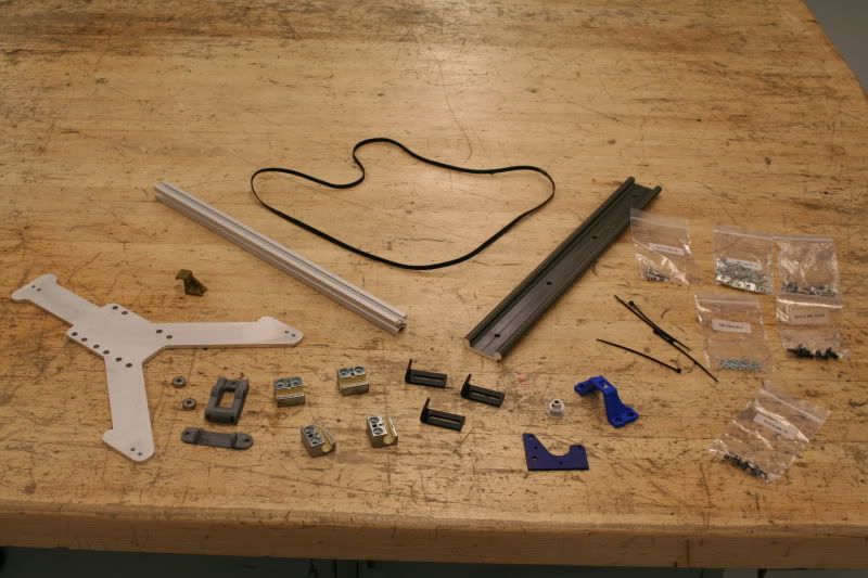
Parts.
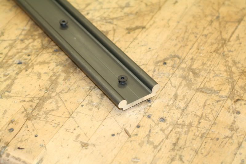
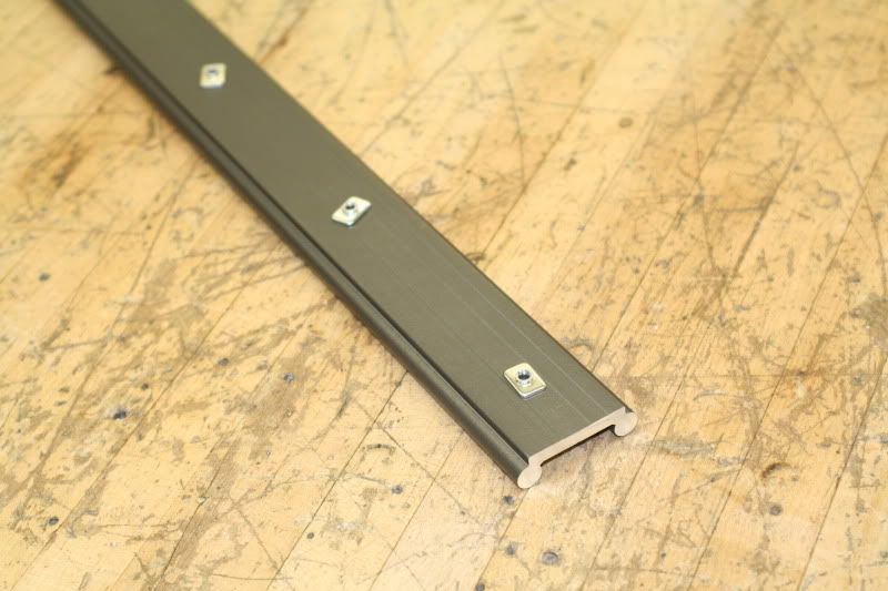
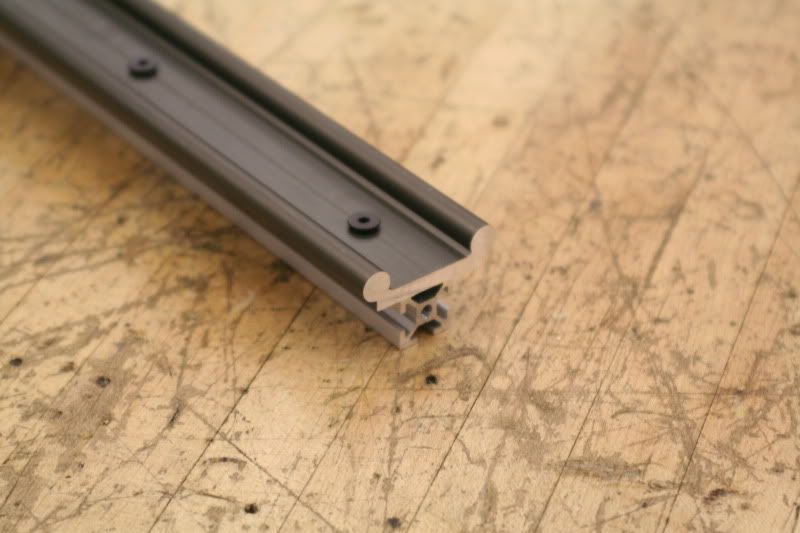
Rail. By now attaching things to the extrusions with the t-nuts is cake.
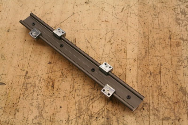
Cars. They slide right on and don't need broken in like the bushings for the z-axis.
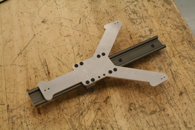
Y plate. I'm not sure if it matters, but in this picture it's upside down- the two empty holes are supposed to be facing the other direction. Haven't figured out what the holes are for yet, so it may not matter. Wasn't hard to get the cars to slide freely- lightly tighten them up and then tighten them all.
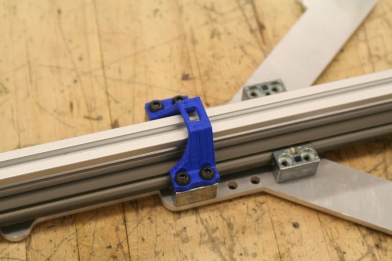
Printed part. The print quality seems pretty poor... easy to attach. This piece is what the belt from the y axis stepper motor attaches to so the y plate moves.
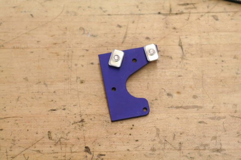
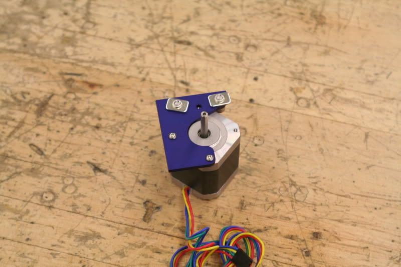
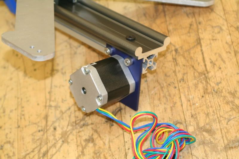
Motor. Can't use a screw in the top hole when mounting the stepper motor because it interferes with the slot in the extrusion.
Completed assembly.
Pretty simple step. Almost looks like a printer!
Time Spent on this step: 30 min.
Total time so far: 5hrs 20 min.
Tuesday, February 19, 2013
Mendelmax 2.0 Z-Axis
Bit of a review first on my thoughts of the kit so far. So far I would rate the kit quality as pretty darn good. Not 5 stars, but a good solid 4. A few of the parts have some minor scratches and on part the laser cutting quality is pretty bad but it seems to be 100% functional. I'm loving putting it together- its like playing with a real fancy erector set!
Instructions at this point leave a LOT to be desired- but again, that is why I'm doing this! It's pretty fun to be involved in the development of the directions- I make notes as I go of any errors or suggestions and then I get on Google Docs and make comments, along with several others who are going through the same process. By the end of it all, I believe the next set of kits sold will have an darn near perfect set of directions.
One other thing I want to mention- the times I'm listing include studying the directions, finding parts in the bags, taking pictures, and making notes. It also includes mistakes I make (which so far have been minimal), meaning I have to take something apart and switch it around.
Assembly of the Z axis.
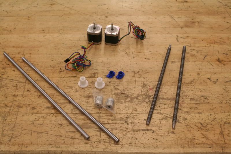
Parts.
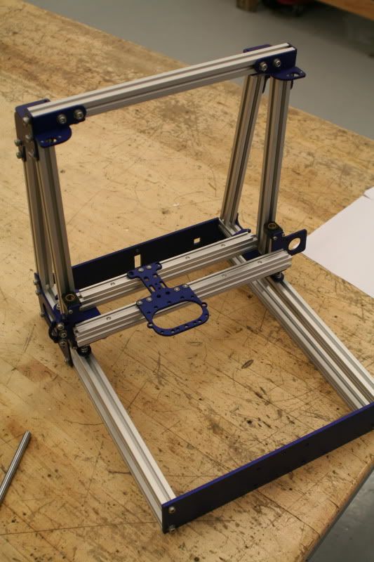
Combine the first two assembly's by setting the x axis in the frame.
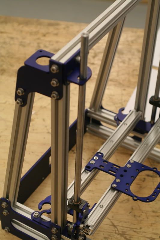
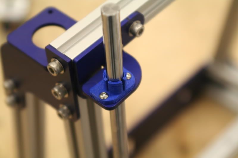
Start adding things! First thing is the bushing rods. They are supposed to be adjusted (by tweaking the bushing on the x-axis) so that they sit in the center of the hole on top.
Bushing rod clamp installed. I later put zip ties around the printed part just to make sure the bushing rods don't pull out.
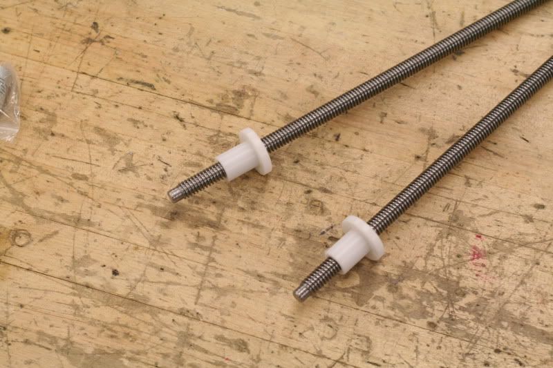
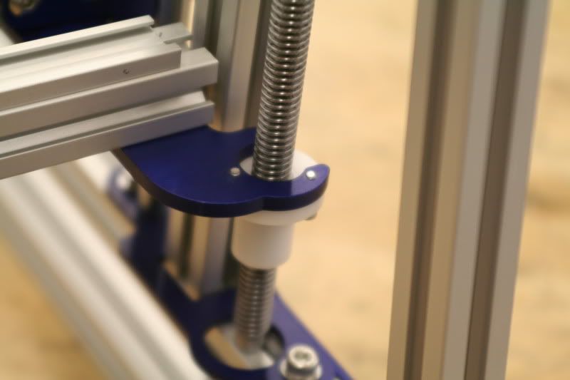
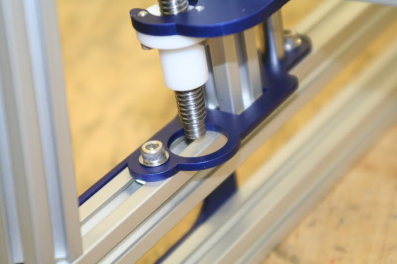
Z screws and accompanying derlinger (?) nuts. Note which end is facing which direction... The other end of the screws has a longer skinnier piece that attaches to the stepper motors.
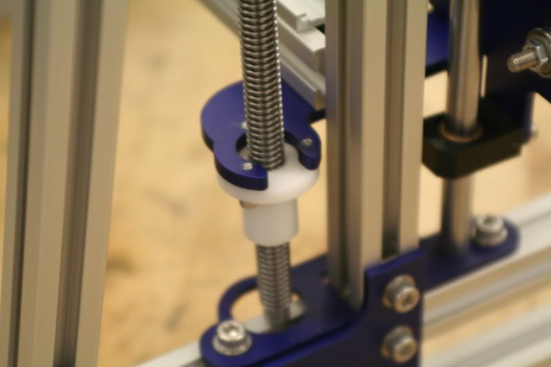
Attached to the x-axis frame.
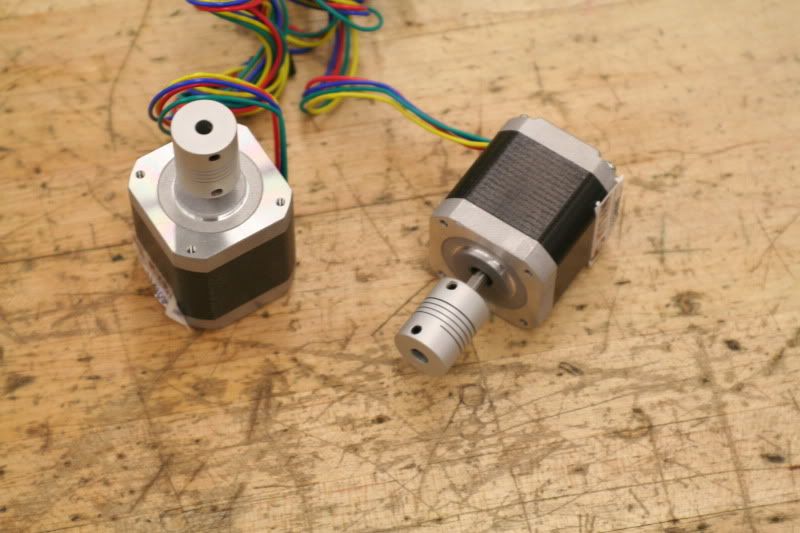
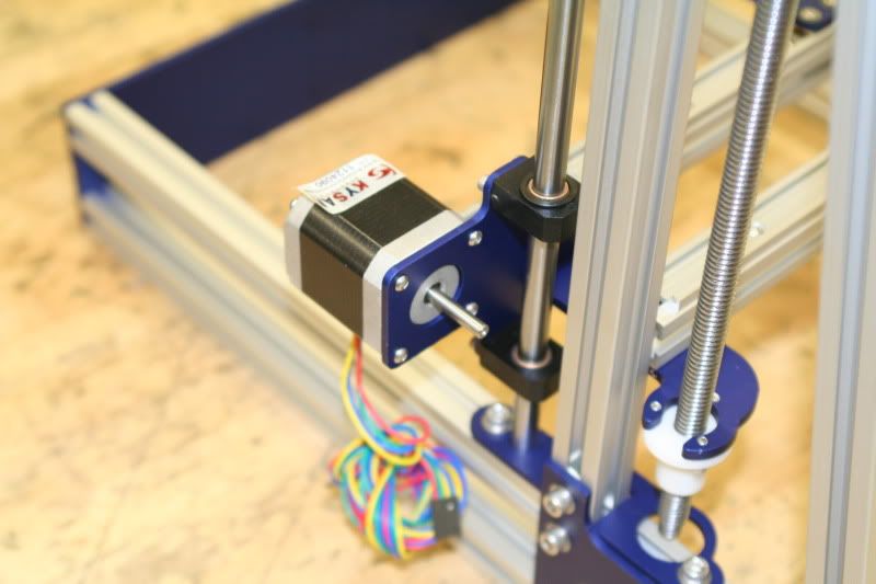
Stepper motors with the couplers installed. The couplers have different size holes- the small hole goes over the motor shaft and the large hole goes over the z-axis screw.
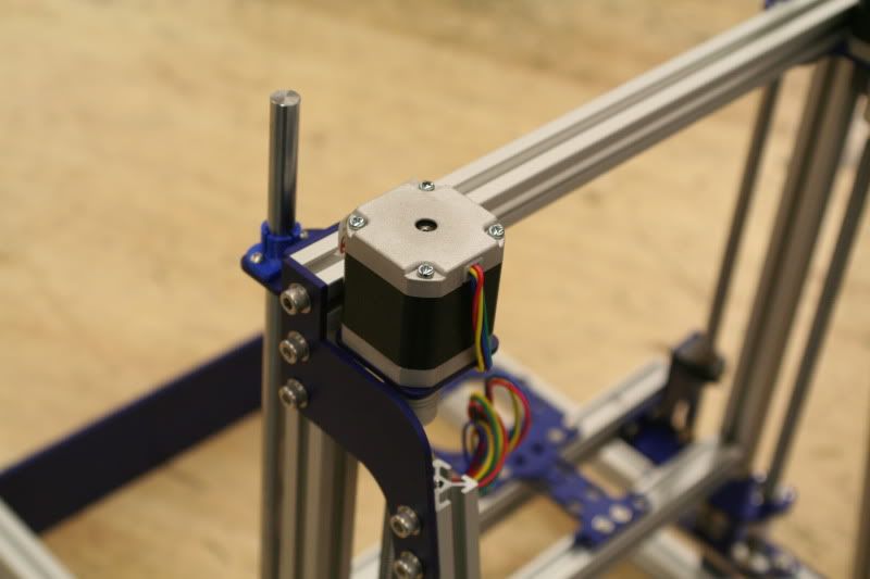
Stepper installed. I had to loosen the motor plate from the frame and slide it around a little to get the motor to drop back into place. Repeat for the other side.
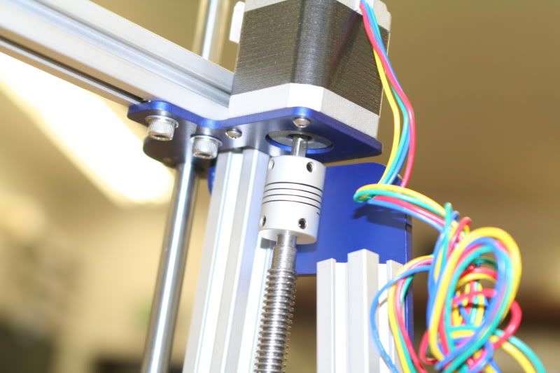
Coupler attached to the screw.
At first I thought this was weird- It looks like there should be something in the big hole to guide the screw, but nothing goes there. The screws don't wobble at all.
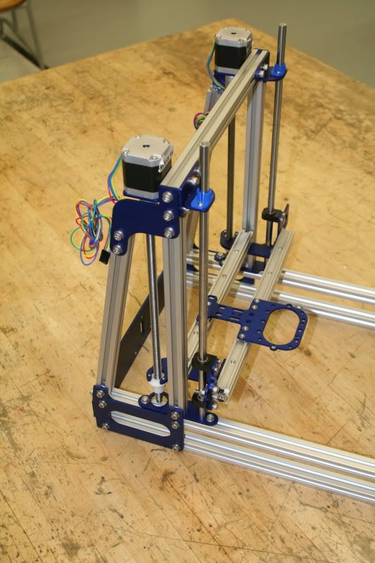
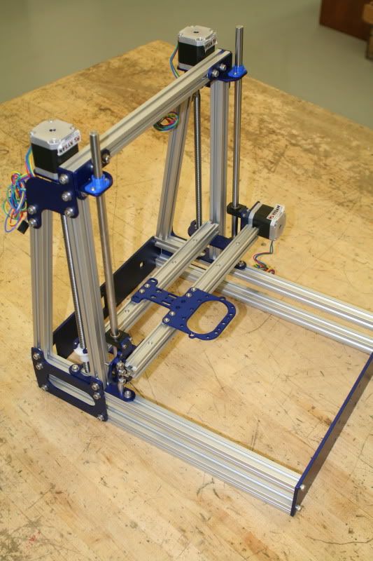
Shot of the completed work so far...
I also installed the x-axis stepper motor. This was supposed to be done during assembly of the x-axis, but I didn't have my stepper motors with me at the time.
Completed assembly so far:
I did have some binding on the z-axis, but I wasn't worried about it at this point. I had a lot of loose screws still and was planning on spending some time when it was more put together to align everything and get everything moving smoothley.
Time Spent on this step: 35 min
Total time so far: 4 hrs 50 min.
Sunday, February 17, 2013
Mendelmax 2.0- X-axis assembly
Assembly of the X axis. Directions here got a little confusing but thats part of the fun when you are helping test something out. A lot of changes have been made to the directions already and have clarified a lot of the questions I had when assembling these parts. Here we go!
Parts.
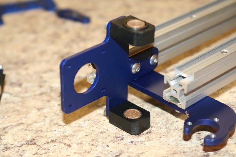
Bushings. This part was pretty confusing- Think I've gotten it figured out now thanks to their support group. They need to be "broken in" because they are very stiff at first. Kinda hard but not impossible. Getting them installed into the bushing blocks was confusing because I didn't understand which direction they were supposed to go in, but that has also already been addressed.
Rails. Pretty straight forward. One thing I discovered later is that you don't need to tighten them now- leave them loose so later when the x plate is installed you can align the rails. This needs to be done the carriage doesnt bind.
These blue things hold the rails together and also hold a special nylon nut that the z-axis screws thread into.
t
Bushing plates prepped and ready to install on the rails.
X cars ready to install. These fit in the rails and act like a bearing as the x plate slides back and forth- keeping it aligned and theoretically, low on friction.
X plate installed on cars and rails.
Belt Tensioner. ***These pictures are wrong- there are supposed to be 5 washers under the bearings to spacer them out from the plate. I will update these pics when I have access to them (posting from an Ipad right now...)
Finished x-axis. The entire thing is put together loose- I was expecting to have to do a bunch of aligning and I was right. As you will find out, it takes some fiddling to get the axis to move freely without binding.
Time Spent on this step: 1 hr 5 min.
Total time so far: 4 hrs 15 min.
Parts.
Bushings. This part was pretty confusing- Think I've gotten it figured out now thanks to their support group. They need to be "broken in" because they are very stiff at first. Kinda hard but not impossible. Getting them installed into the bushing blocks was confusing because I didn't understand which direction they were supposed to go in, but that has also already been addressed.
Rails. Pretty straight forward. One thing I discovered later is that you don't need to tighten them now- leave them loose so later when the x plate is installed you can align the rails. This needs to be done the carriage doesnt bind.
These blue things hold the rails together and also hold a special nylon nut that the z-axis screws thread into.
t
Bushing plates prepped and ready to install on the rails.
X cars ready to install. These fit in the rails and act like a bearing as the x plate slides back and forth- keeping it aligned and theoretically, low on friction.
X plate installed on cars and rails.
Belt Tensioner. ***These pictures are wrong- there are supposed to be 5 washers under the bearings to spacer them out from the plate. I will update these pics when I have access to them (posting from an Ipad right now...)
Finished x-axis. The entire thing is put together loose- I was expecting to have to do a bunch of aligning and I was right. As you will find out, it takes some fiddling to get the axis to move freely without binding.
Time Spent on this step: 1 hr 5 min.
Total time so far: 4 hrs 15 min.
Subscribe to:
Posts (Atom)