title

Motorcycles, tools, and garages! A little bit of everything mechanical and technical.

Thursday, February 28, 2013

Mendelmax 2.0 / RUMBA Board Firmware & Software

I'm going to preface this post by saying 2 things: 1.  I am NOT a programmer, and 2.  This was a royal pain in the butt for me.  On the bright side, I think I actually remembered some things from the C++ class I managed to (I think...) keep my eyes open in, and they came in handy.   I opted to use a RUMBA printer control board (no idea why... seems like someone said its the one to have?).  It is still a brand new, fairly untested control board and as such there isn't a lot of info out there on it.  It is supposed to be extremely similar to the RAMPS 1.4 board, but I wouldn't be the one to ask what the similarities / differences are.  I did have a combination of issues with the board- it would appear that either the included USB cable is bad or the USB connector on the board is wonky.  Ended up using a different USB cable and cutting the end off and attaching to the optional pins on the board.  Seems to be working fine now.  Sounds like there have been a few others with bad USB cables, not sure if anyone else has had issues with the connector though.

Alright... so here's the how to get drivers / firmware uploaded... After spending 3 frickin hours last night trying to get this to work only to discover a bad usb cable this morning. Not going to count that 3 hours in the overall time either.

First step: Download the RUMBA drivers from here: http://reprap.org/wiki/File:RRD-RUMBA_USB_DRIVER.zip

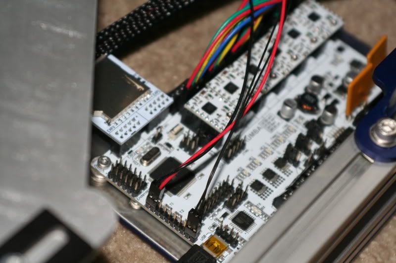
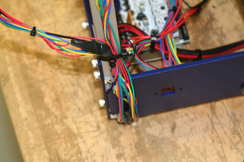
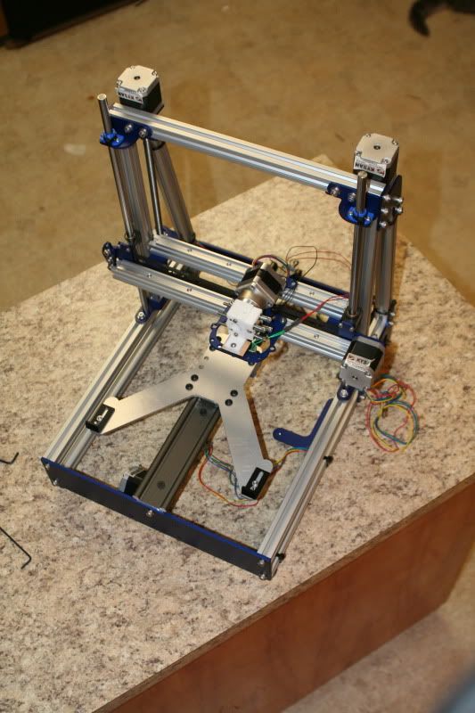
This part isn't required, but by switching this jumper you don't have to have the printer plugged into power- the RUMBA board is powered by the USB. You can just barely see the pin over the red wire, next to the x axis stepper driver. It's pretty clearly labeled- one side says stand alone, the other usb power. Switch it to usb power so you don't have to have the printer plugged in.


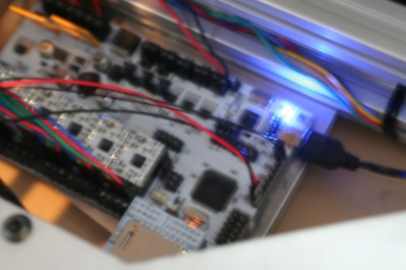
Plug the usb cable in, and you should get a nice blue light on the board!


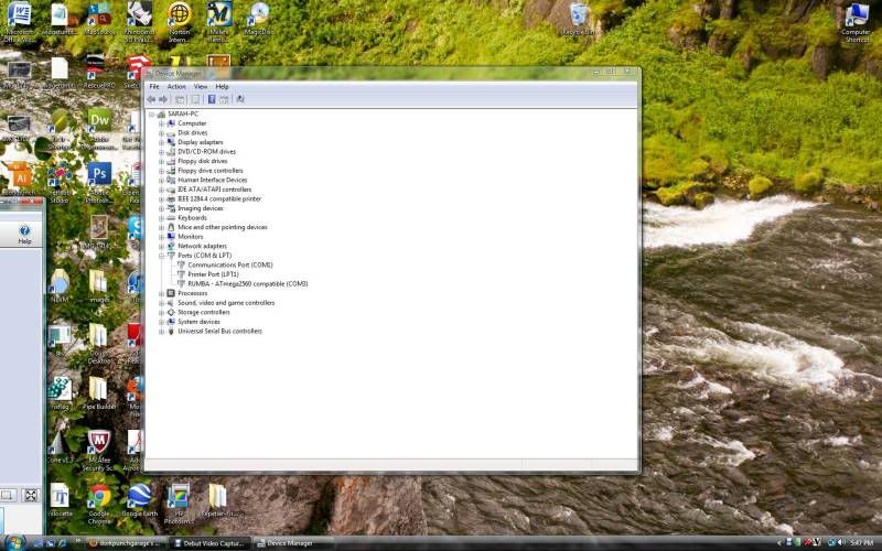
Time to install the drivers. Remember were you saved them to! If when you plugged in the usb you got a message saying unrecognized device, click it and choose either properties or update drivers. If you missed it, open the "Device Manager" in Windows, and you should see on the list something like this:


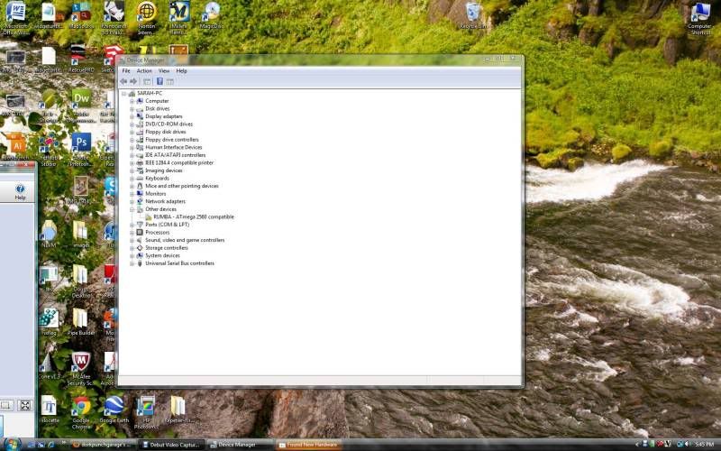
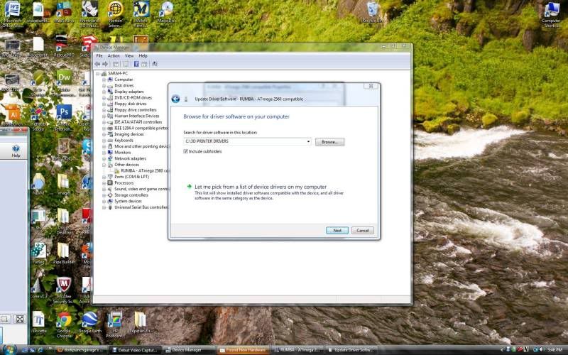
See the RUMBA xxxxxxxxxxx with the yellow mark under Other Devices? Right click and select either properties or update driver.


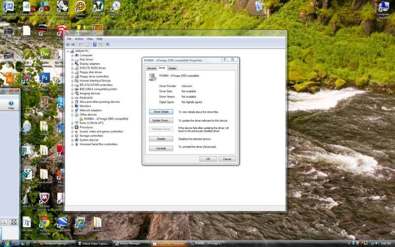
Go through the prompts and show it where you saved the drivers to install.


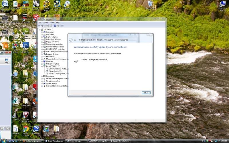
There it is! MAKE A NOTE OF WHICH COM IT SAYS IT'S USING!!!! In my case, it is set to COM 3.


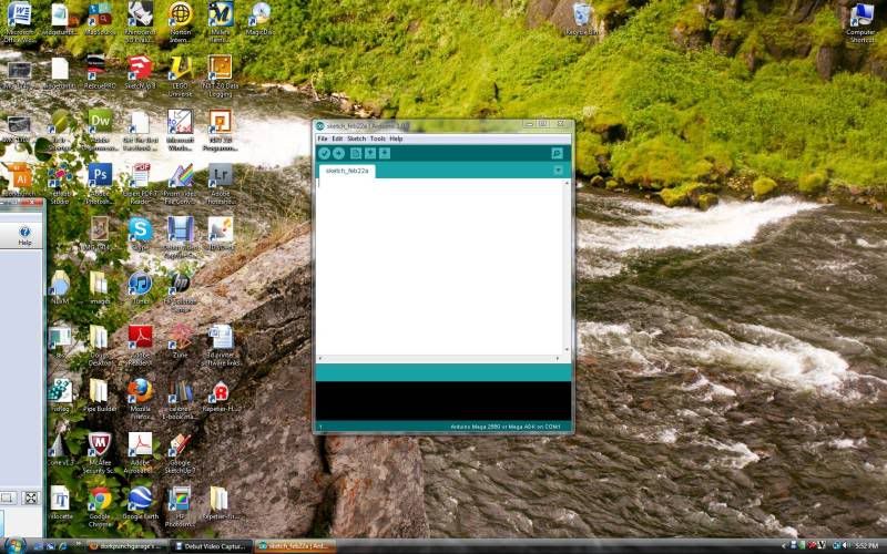
Next step. Download and install the latest arduino IDE- here is the most current version at the moment: http://code.google.com/p/arduino/downloads/detail?name=arduino-1.0.3-windows.zip

When you run it it looks like this:


Next, download and install the Marlin FIRMWARE. BOTH are available here: https://github.com/ErikZalm/Marlin/tags

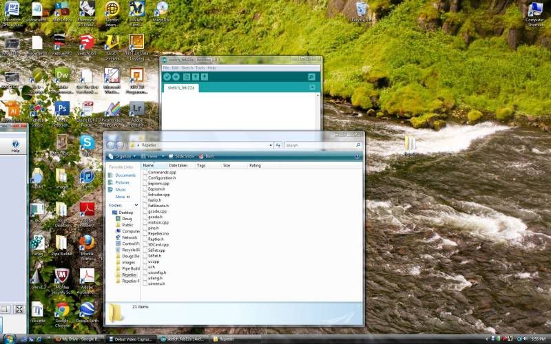
When you unzip it it gives you a folder full of weird files like this:


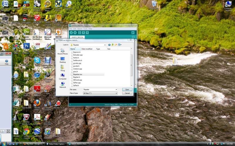
Go back to the Arduino software, and using it, open the marlin.ino file in the firmware folder you just unzipped.  The pic below shows the Repetier firmware, which should also work but will have some differences.


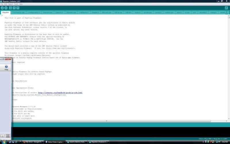
This is what you get. A buncha Greek. Or is that Geek?


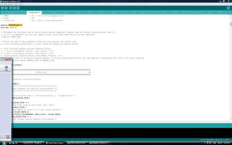
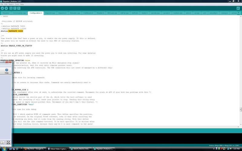
We need to change a couple of settings. First, click on the Configuration.h tab. Scroll down and find the "#define MOTHERBOARD XXX" and change the number where the X's are (mine defaulted to 33) to 80.


Now scroll way down and find the Communication configuration section, and set the baudrate. I changed it from "#define BAUDRATE 250000" to "#define BAUDRATE 56000", cause it was recommended SOMEWHERE in the all the reading I did...


Now for the big step. You have to go to the RUMBA wiki and copy the pins.h information. Find it here: http://reprap.org/wiki/RUMBA#RUMBA_F..._Configuration Copy the entire section under Rumba Pin Configuration.

Now go back to the Arduino software, and click the pins.h tab. You may have to use the down arrow at the upper right hand corner of the screen to find it on the list.

The pins.h seems to have a crap load of different option for different boards. I just scrolled down until I found the numerical order of things (remember, we set the motherboard to 80?) so the stuff I copied I pasted between option 70 and 331.   I think you can past it between any other set of info.


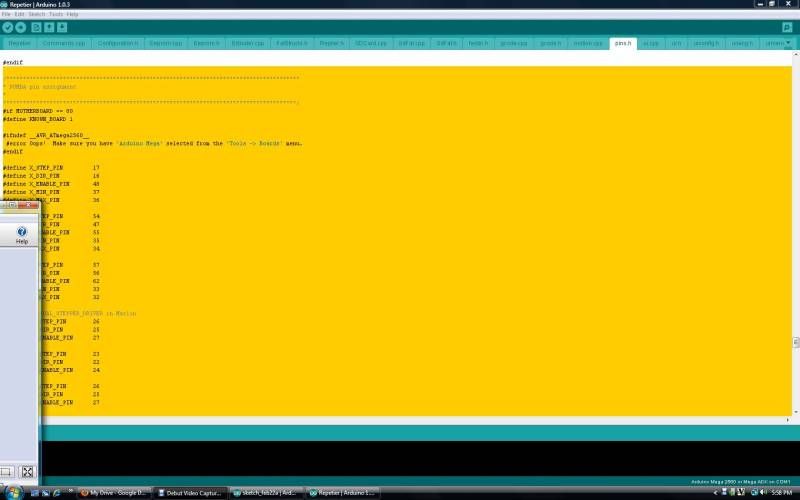
Are we TOTALLY LOST YET!? Cause I sure am!

Gets a bit easier now. Once all those changes are made, with the printer hooked up just click upload. It'll take a minute or two but when it says its done, you're ready for the next step.

Download and install the Repetier SOFTWARE, available here:  http://www.repetier.com/download/
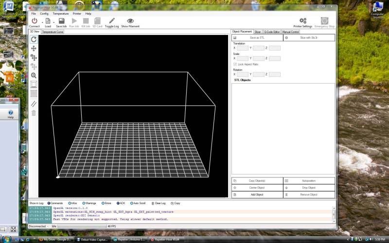
. Open the software- looks somethin like this.  PLEASE NOTE:  There is another print control software called Pronterface, available here:  http://koti.kapsi.fi/~kliment/printrun/ .  It seems great.  I like the Repetier software better but I'm having some issues getting it to finish prints... More on this later.


Now we need to set the software up to communicate with the printer. Click configure, choose printer, and this menu pops up.


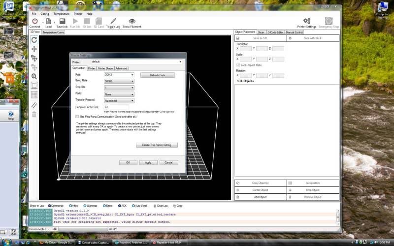
You will need to change the COM to the correct one (mine was COM 3) and change the baud rate to match whatever you set it to.

Apply the settings, and you should be ready! Plug the printer in to power, and click connect. It should connect and the connect button changes to "disconnect. Scootch over to the manual control tab, and try moving axis around!!!

May seem like a lot, but now that I've done it it really wasn't that bad. There is a TON of info on the Repetier website on installing and the hows and whys of printer software, available here: http://www.repetier.com/documentatio...-installation/

Careful with that link though, my brain almost exploded...

The sad part? I still am going to have to modify the firmware to set up the thermistors (thermometers on the extruder and heated bed) AND figure out how to set it up so that BOTH z axis stepper motors work at the same time. Ug. Marching forward...


One other thing- the guys at Makers Tool Works have been awesome at helping me out with this... They have a webchat channel that anytime so far I've logged in, someone was right there to help me out. Great customer service!
Time Spent on this step: Lets call it 1 hr.
Total time so far: 14 hrs. 15 min.

Wednesday, February 27, 2013

Mendelmax 2.0 Wiring and Electronics

Here's where it gits a bit hairy for me...  Mechanical end of things was cake.  Wiring / electronics / software / coding... Been a while and when I did it before lets just say it wasn't my favorite thing in the world.  Got some bits made and installed. Battery died on my camera, so these were taken with my Ipad- sorry for the quality.

Made an adapter to fit the electronics board to the included mount.  The blue mount is designed for a RAMPS board, I got a RUMBA.  This is temporary, plan on printing one out of plastic when I get the printer going.


Installed. It's spacered up with washers so the contacts on the back side don't ground out.


Made some temporary mounts for the power supply since mine are missing...  Makerstoolworks.com has already shipped me the missing mounts so hopefully I will see them soon!


Turns out this piece doesn't need the t-nut, it holds itself in place with the little hook.


Which means, taking off the front plate like this was totally unnecessary.


Power supply and RUMBA board installed.


Spent some MORE time fiddling with axis trying to get them to run smoother and also running wires. Trying different things out as far as routing... still haven't settled on anything but I think I've got it figured out. I'm going to have to extend a few wires to reach the board...

Took some vids today too.


X-axis operation.


I did also run the wires from the power supply to the RUMBA board. Feel like I have a million little things to do still but I think I'm getting close. Was hoping to get more done in the time I spent on it today, but c'est la vie.

Time Spent on this step: 2 hrs.
Total time so far: 11 hrs. 45 min.

More wiring...

Had to lengthen some wires, add some ends, and route a few more pieces.


Put this cover thingy over the wires from the heated bed. No idea if that's what its for, but it looks good to me.


Got everything sorted out and routed where I think it is out of the way of moving parts.


SOOO CLOSE!


It MOVES!


Now time for software.


Time Spent on this step: 1 hr. 30 min.
Total time so far: 13 hrs. 15 min.

Man, that time sure adds up quickly!

Sorry some of the pics aren't working, I've fixed the account so they should show up shortly...


Tuesday, February 26, 2013

NOT 3D related...

That printer is starting to drive me a little bit buggy...

End of the Tri is upon us. Finals tomorrow, shop cleanup the next day, new students on Monday. Ug. Tri's are waayayyy to short to get anything productive done. That said, here's a couple of the shields from this tri's metals classes.

Photobucket

Some of them turned out great. Others could use a little work- mainly on the following instructions end of things. Hey, they're 13 years old! You can't tell, but several have leather straps on the back, a few have hooks for hanging on the wall. Some used rivets to make letters too.

The round one was a real booger to do. Been playing with the edge former and a student asked if he could make a Captain America shield- that's as close as we could get. Rolling the edge was tough, but now that I've done it once I may let a few more do it again.

Awe heck, why not. The *brrrppppp-bbbbbbbbbbrrrrrrrrrpppppppp* of the printer tends to draw a crowd...

Photobucket

Getting closer. Troubleshooting a few odd bits but finally getting some prints off of it!

Sunday, February 24, 2013

Makergear Plastruder, Part 2.


Bit of a step backwards, but I have to finish up the plastruder because its time to put it in!

Parts.


Install and tighten the nozzle using the 2 lock nuts to hold the tube while tightening the nozzle, then remove the nuts.


Heater.  Do you remember all the fun steps getting this little guy put together?!  Sheesh.


Mount. The mount and the nozzle need to be tight so the melted plastic doesn't squish out.


This was kind of tricky. You can barely see the thermistor- it needs to be touching the nozzle and is held on by the "Kapton" tape. Pllleennnnty of tape included.


Installed.


Insulation. Real easy, just slide it over.


Had to install a few connectors, including soldering the teensy bits to the wire first.


Again, if you buy a plastruder, pay the extra $10 and have it pre assembled! 

Installation. The screws make a little more sense now- the plate that the plastruder bolts to is a little thick. Just have to make sure the screws don't contact the motor.


Done.


As you can see I pulled the bed back off to run wires. Lots of them going all different directions. I'll have to mount the power supply and RUMBA board, then I can finalize the wire routing, plug everything in, and try it out. 

Time Spent on this step: 1 hr.
Total time so far: 9 hrs. 45 min.